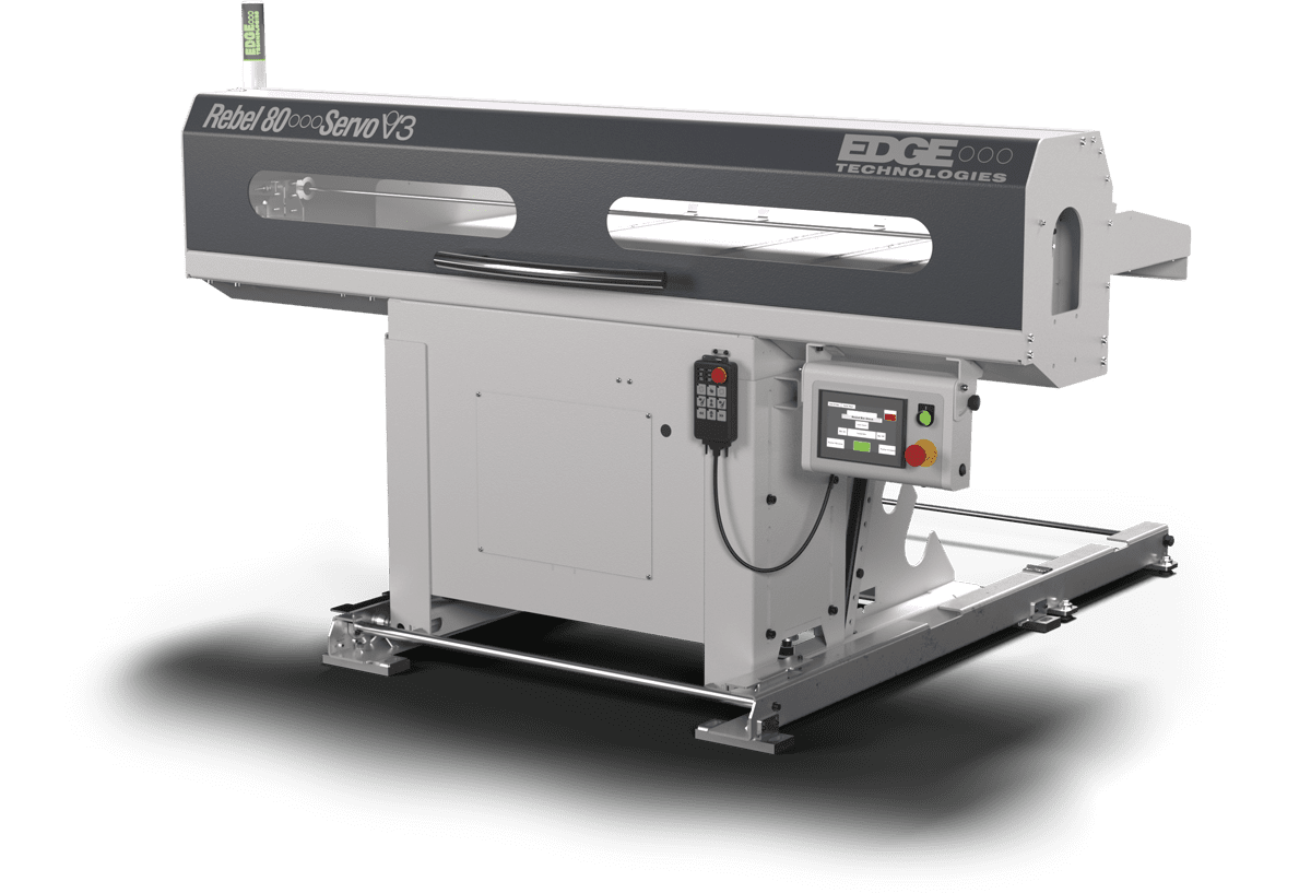
Rebel 80 Servo V3 Loader
The Rebel 80 Servo V3 is a compact bar loading system for CNC lathes. Features include a large magazine capacity, easy programming, easy centerline adjustment, remote control axis jog, all electric operation, linear feed, Servo drive, and a soft load design.
The Rebel 80 Servo combines advantages of auto bar loading with a small footprint and an economical price. This short loader is built to feed bars in the diameter range of 8-80mm.

Remote Pendant
The intuitive remote control facilitates seamless interaction between the bar feeder and the CNC lathe, ensuring a safe and efficient production process.
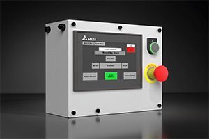
Touchscreen HMI
User-friendly software delivers fast setup on easier jobs and 300-part storage.
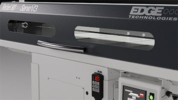
Visible loading
Two polycarbonate windows allow you to observe functionality.
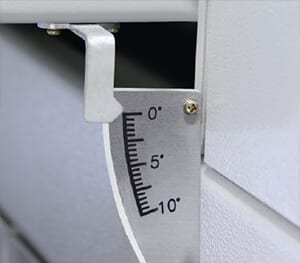
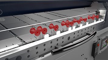
Soft Load
Material is lifted up to centerline height. Manual diameter adjustment is indicated in Metric and English increments.The magazine incline is adjustable; enabling the loader to "soft-load" large diameter bars.
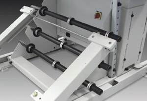
Spindle Liner Storage
Rebel 80 Servo V3 includes storage for (3) Spindle Liners under magazine
Optimized material guidance
Rebel 80 Servo V3 uses rollers in its magazine, this feature increases barstock stability, heavier material loads, and softer material.
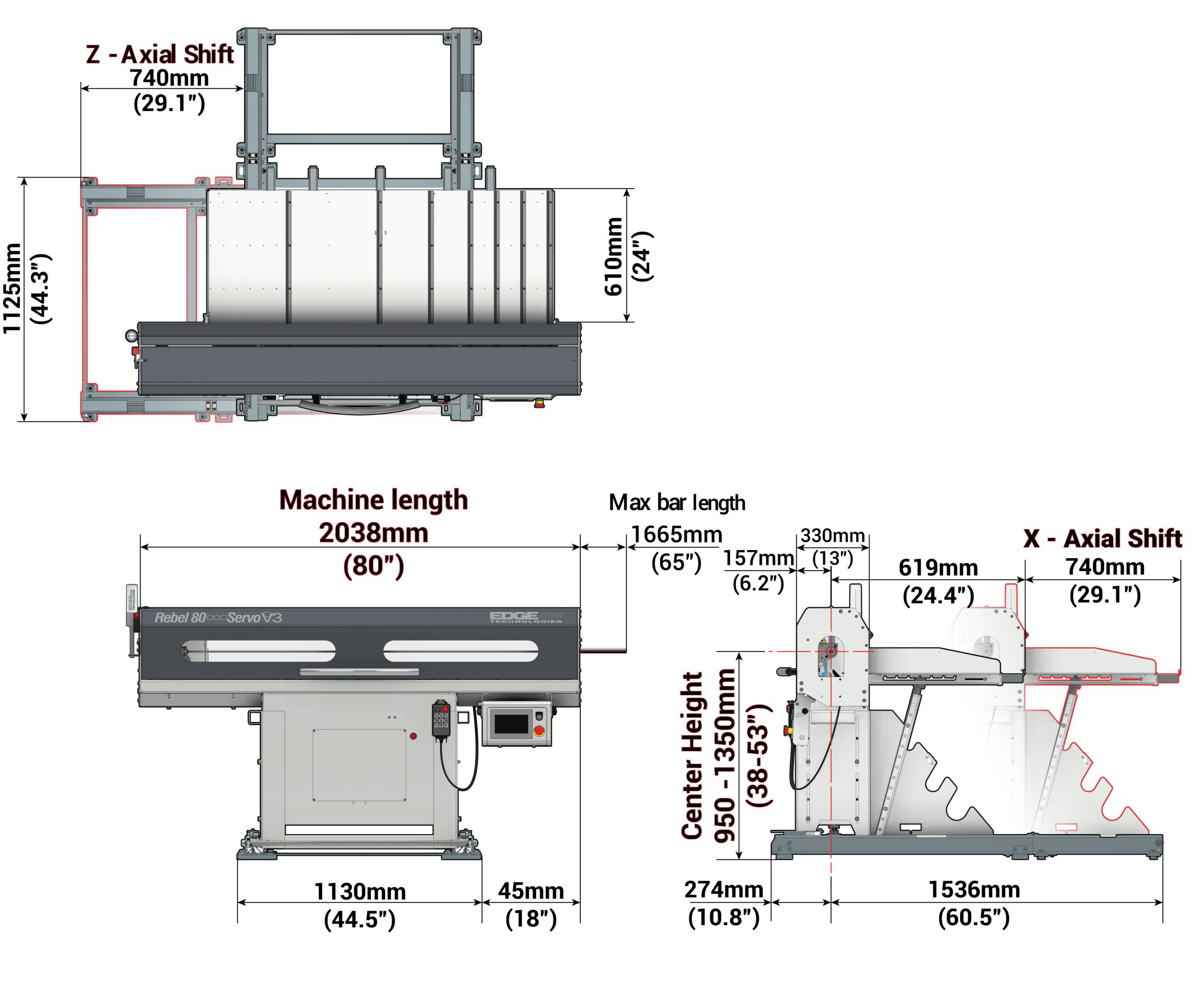
| Bar diameter capacity: | 8 mm to 80 mm (.315” to 3.150”) |
| Maximum bar length: | 60” (not to exceed spindle length) |
| Magazine rack capacity: | 762 mm (30”) |
| Bar loading cycle time: | 20 seconds |
| Power consumption: | 1 kW – (1.5 kVA) |
| Operating voltage: | 230V/60Hz 3-phase |
| Control voltage: | 24V DC |
| Machine footprint: | 84” x 48” |
| Machine weight: | 1,100 lbs |
| Spindle center height: | 875 mm – 1350 mm (34.5” – 53.125”) |
| Bar weight: | 150 lbs. per bar (1500 lbs. magazine max) |
Standard Features |
Available Options |
|---|---|
| Touch screen control – with 300 part program storage | Lathe spindle liner (liner size determined by customer) |
| All electric operation – no shop air required | Dual channel safety kit |
| Fixed piece feed-out and sub-spindle mode | High voltage kit (required for some lathes) |
| Lathe spindle speed can be maximized | V-tray kit (required on lathes that have a gap between sheet metal & spindle – 6” max) |
| Material length can be uniform or random | Extended V-tray kit (required on lathes that have a gap between sheet metal & spindle that exceeds 6”) |
| Material can be round, hexagonal or shaped | Risers required with tall stands for lathes with spindle center greater than 1350 mm |
| (2) Pushers included: 10 mm, 19 mm | Tall stands for lathes with spindle center greater than 1250 mm |
| Standard X axial shift device (Z optional) | 6 mm pusher for diameters of 8 – 10 mm |
| (XL) Pusher kit – adds 500 mm to pusher length | |
| Serial interface Ethernet connection with embedded PC | |
| Coolant collector extension kit (required with extended liner) |
Manual Request Form
Download Brochure
How do I 'home' the bar feeder (also referred to as 'resetting the zero point')?
- Begin with the long or the short pusher forward about a foot.
- Press the [Manual] block in the upper left-hand corner of the screen. This will bring up a new screen.
- Press the [Maint Screen] button to bring up the maintenance screens.
- Press the [Jog/Set Pusher] button. The screen will display the pusher menu.
- Press the top right [Disable Servo] button.
- By hand, move the long pusher to within ½ inch of the home proximity switch at the rear of the bar pusher’s stroke.
- Press the top right button again, which now says [Servo Disabled, to restore the servo drive to operation.
- Press the top left button, it will say either [Reference position lost] or [Reference OK]. The bar pusher will move very slowly toward the home proximity switch until it reaches the hard stop. During this movement the [Reference OK] or [Reference position lost] button will blink. When the movement is complete the button will be steady and say [Reference OK]. The position on the screen at this point will be negative 1.0mm or the inch equivalent. The pusher position must be 0 before the V-tray will operate.
- Push the [Pusher Advance] button on the screen until the pusher position is greater than 2.0mm.
- Push the [Go to home position] button and the pusher will return to zero.
- Press the [Maint Screen] button, then the [Start Screen] button to exit.
How do I shorten my remnant length?
The remnant length is controlled by the parameters:
- “Bar End Position Setup” and “Finish Product Length Setup”
- The distance from the chuck or guide bushing the cut-off occurs
- The length of the material in the guide channel
The bar end position setup point is the farthest the bar pusher can travel forward into the lathe. The part length is the sum of the overall part length, the width of the cut-off tool and the amount of material left for facing.
When the pusher doesn’t have enough travel left to move the distance in the part length parameter before reaching the front limit position the [End of Bar] signal is sent.
If the remnant is too long, verify the bar end position setup parameter and the part length parameter. Keep in mind that on all lathes there will be a certain amount of unusable material. This unusable length can be measured by moving the bar pusher to the bar end position setup point and measuring from the cut-off tool to the end of the bar pusher.
For Swiss-type lathes, move the headstock to feeding position and measure from the back of the cut-off tool to the end of the bar pusher. This measurement is your minimum remnant length. The remnant length can be up to one part-length longer than the minimum, depending on how much material is remaining.
How do I set my 'end of bar' (EDGE: 'max end of bar')?
- Before beginning reference (re-zero) the bar pusher.
- For sliding headstock machines only, move the headstock into overtravel toward the guide bushing.
- For all machines, move the bar pusher forward with no material in the channel or spindle until the end of the bar pusher is at the back of the clamping surface of the lathe collet.
- Record the pusher position from the screen and enter the value in the [Bar End Position Setup] parameter located in the [F2 Fixed Parameters].
- To get to the parameter press the [F2]* button from the main screen, then use the [F2] button to scroll through the pages to the parameter.
*Note that the [F2] section is protected by the password 258.
How do I set the 'top cut' position (first insert position / facing length)?
The facing position controls where the new bar stops in the lathe during a bar change.
For Swiss-type lathes:
- The value of the parameter is a measurement of the distance from the facing flag to the face of the guide bushing minus 2 inches.
For fixed headstock lathes:
- Measure the distance from the facing flag to the face of the collet.
- Enter the measurement in the [Facing Position] parameter in the [F2 Fixed Parameter] section.
- To get to this parameter press the [F2] button and enter the password 258.
- The screen will change to show the Facing Position parameter.
- Type the new value and press [Enter] (F9 key to the right of the 0 key).
- Press the [F3] key to return to the main screen.
What parameters or settings do I have to change when setting up a new job?
When changing to a new job, the [Finished Product Length] parameter in the [F1 User] parameters should be changed.
The proper setting is the sum of the overall part length + the width of the cut-off tool + any facing stock used. This dimension reflects the total amount of material required to make and cut off one part.
The facing length may need to be altered in case of a left-handed cutoff tool or to provide a longer “stick-out” of material on the bar reload.
- Locate the [Safety Position Setup] parameter located in the [F2 Fixed] parameters.
- Adjust the parameter higher or lower as needed. This parameter requires the password – 258.
The [Open Collet Speed] and [Open Collet Torque] parameters normally are not changed but can adjusted in special cases such as extremely small or large diameters or flexible material. These parameters can be found in the [F1 User] parameters.
Explain the dwells I need to have present in my lathe program to accommodate the bar feeder?
- For fixed headstock lathes a dwell is required in the part program to give the bar feeder time to advance the material for the next part before the collet closes.
- The length of dwell is dependent on the length of the part to be feed out.
- A short dwell is needed to allow the bar pusher time to retract from the material before the spindle starts to prevent damage to the pusher.
How do you set the chain/belt tension on my bar feeder?
The drive belt is adjusted by moving the front pulley:
- Loosen the bolts on the top and bottom of the vertical shaft of the pulley.
- Two bolts go from the front of the bar feeder through threaded holes in the shaft, one above and one below the pulley.
- Tighten the screws equally to draw the pulley toward the front of the bar feeder.
- Retighten the bolts at the top and bottom of the shaft when done.
- Proper adjustment is 3/4 to 1 inch deflection when pressing on the belt at the midway point when the bar pusher carriage is at the home position.
- Re-zero the bar pusher after making the adjustment.